A belt is a loop of flexible material used to link two or more rotating shafts mechanically, most often parallel. Belts may be used as a source of motion, to transmit power efficiently, or to track relative movement. Belts are looped over pulleys and may have a twist between the pulleys, and the shafts need not be parallel.
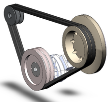
A pair of vee-belts
In a two pulley system, the belt can either drive the pulleys normally in one direction (the same if on parallel shafts), or the belt may be crossed, so that the direction of the driven shaft is reversed (the opposite direction to the driver if on parallel shafts). As a source of motion, a conveyor belt is one application where the belt is adapted to carry a load continuously between two points.

flat belt
Power Transmission
Belts are the cheapest utility for power transmission between shafts that may not be axially aligned. Power transmission is achieved by specially designed belts and pulleys. The demands on a belt drive transmission system are large and this has led to many variations on the theme. They run smoothly and with little noise, and cushion motor and bearings against load changes, albeit with less strength than gears or chains. However, improvements in belt engineering allow use of belts in systems that only formerly allowed chains or gears.
Flat belt drive in the machine shop at the Hagley Museum.
Power transmitted between a belt and a pulley is expressed as the product of difference of tension and belt velocity:

where, T1 and T2 are tensions in the tight side and slack side of the belt respectively. They are related as:

where, μ is the coefficient of friction, and α is the angle subtended by contact surface at the centre of the pulley.
Pros and Cons
Belt drive is simple, inexpensive, and does not require axially aligned shafts. It helps protect the machinery from overload and jam, and damps and isolates noise and vibration. Load fluctuations are shock-absorbed (cushioned). They need no lubrication and minimal maintenance. They have high efficiency (90-98%, usually 95%), high tolerance for misalignment, and are of relatively low cost if the shafts are far apart. Clutch action is activated by releasing belt tension. Different speeds can be obtained by stepped or tapered pulleys.
The angular-velocity ratio may not be constant or equal to that of the pulley diameters, due to slip and stretch. However, this problem has been largely solved by the use of toothed belts. Temperatures ranges from −31 °F (−35 °C) to 185 °F (85 °C). Adjustment of center distance or addition of an idler pulley is crucial to compensate for wear and stretch.
Flat Belts
Flat belts were widely used in the 19th and early 20th centuries in line shafting to transmit power in factories. They were also used in countless farming, mining and logging applications, such as bucksaws, sawmills, threshers, silo blowers, conveyors for filling corn cribs or haylofts, balers water pumps (for wells, mines, or swampy farm fields), and electrical generators. Flat belts are still used today, although not nearly as much as in the line shaft era. The flat belt is a simple system of power transmission that was well suited for its day. It can deliver high power at high speeds (500 hp at 10,000 ft/min or 373 kW at 51 m/s), in cases of wide belts and large pulleys. But these wide-belt-large-pulley drives are bulky, consuming lots of space while requiring high tension leading to high loads, and are poorly suited to close-centers applications, so V-belts have mainly replaced flat-belts for short-distance power transmission; and longer-distance power transmission is typically no longer done with belts at all. For example, factory machines now tend to have individual electric motors.
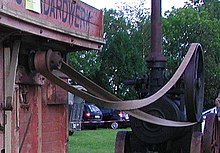
The drive belt: used to transfer power from the engine's flywheel. Here shown driving a threshing machine.
Because flat belts tend to climb towards the higher side of the pulley, pulleys were made with a slightly convex or "crowned" surface (rather than flat) to allow the belt to self-center as it runs. Flat belts also tend to slip on the pulley face when heavy loads are applied, and many proprietary belt dressing were available that could be applied to the belts to increase friction, and so power transmission.
A small section of a wide flat belt made of layers of leather with the fastener on one end, shown in an exhibit at the Suffolk Mills in Lowell, Massachusetts.
Flat belts were traditionally made of leather or fabric. Today most are made of rubber or polymers. Grip of leather belts is often better if they are assembled with the hair side (outer side) of the leather against the pulley, although some belts are instead given a half-twist before joining the ends (forming a Möbius stri), so that wear can be evenly distributed on both sides of the belt. Belts ends are joined by lacing the ends together with leather thonging (the oldest of the methods), steel comb fasteners and/or lacing, or by gluing or welding (in the case of polyurethane or polyester). Flat belts were traditionally jointed, and still usually are, but they can also be made with endless construction.
Rope Drives
In the mid 19th century, British millwrights discovered that multi-grooved pulleys connected by ropes, outperformed flat pulleys connected by leather belts. Wire ropes were occasionally used, but cotton, hemp, manila hemp and flax rope saw the widest use. Typically, the rope connecting two pulleys with multiple V-grooves was spliced into a single loop that traveled along a helical path before being returned to its starting position by an idler pulley that also served to maintain the tension on the rope. Sometimes, a single rope was used to transfer power from one multiple groove drive pulley to several single or multiple groove driven pulleys in this way.
In general, as with flat belts, rope drives were used for connections from stationary engines to the jack shafts and line shafts of mills, and sometimes from line shafts to driven machinery. Unlike leather belts, however, rope drives were sometimes used to transmit power over relatively long distances. Over long distances, intermediate sheaves were used to support the "flying rope," and in the late 19th century, this was considered quite efficient.
Round Belts
Round belts are a circular cross section belt designed to run in a pulley with a 60 degree V-groove. Round grooves are only suitable for idler pulleys that guide the belt, or when (soft) O-ring type belts are used. The V-groove transmits torque through a wedging action, thus increasing friction. Nevertheless, round belts are for use in relatively low torque, situations only and may be purchased in various lengths or cut to length and joined, either by a staple, a metallic connector (in the case of hollow plastic), gluing or welding (in the case of polyurethane).. Early sewing machines utilized a leather belt, joined either by a metal staple or glued, to great effect.
V-Belt
V belts (also style V-belts, vee belts, or, less commonly, wedge rope) solved the slippage and alignment problem. It is now the basic belt for power transmission. They provide the best combination of traction, speed of movement, load of the bearings, and long service life. They are generally endless, and their general cross-section shape is trapezoidal (hence the name "V"). The "V" shape of the belt tracks in a mating groove in the pulley (or sheave), with the result that the belt cannot slip off. The belt also tends to wedge into the groove as the load increases—the greater the load, the greater the wedging action—improving torque transmission and making the V-belt an effective solution, needing less width and tension than flat belts. V-belts trump flat belts with their small center distances and high reduction ratios. The preferred center distance is larger than the largest pulley diameter, but less than three times the sum of both pulleys. Optimal speed range is 1,000–7,000 ft/min (300–2,130 m/min). V-belts need larger pulleys for their thicker cross-section than flat belts.

Belts on a Yanmar 2GM 20 Marines Diesel engine .
For high-power requirements, two or more V-belts can be joined side-by-side in an arrangement called a multi-V, running on matching multi-groove sheaves. This is known as a multiple-V-belt drive (or sometimes a "classical V-belt drive").
V-belts may be homogeneously rubber or polymer throughout, or there may be fibers embedded in the rubber or polymer for strength and reinforcement. The fibers may be of textile materials such as cotton, polyamide (such as Nylon or polyester or, for greatest strength, of steel or aramid (such as Twaron or Kevlar).
When an endless belt does not fit the need, jointed and link V-belts may be employed. Most models offer the same power and speed ratings as equivalently-sized endless belts and do not require special pulleys to operate. A link v-belt is a number of polyurethane/polyester composite links held together, either by themselves, such as Fenner Drives' PowerTwist, or by metal studs, such as Gates' Nu-T-Link. These provide easy installation and superior environmental resistance compared to rubber belts and are length adjustable by disassembling and removing links when needed
 A multiple-V-belt drive on an air compressor
V-Belt History
Trade journal coverage of V-belts in automobiles from 1916 mentioned leather as the belt material, and mentioned that the V angle was not yet well standardized.] The endless rubber V-belt was developed in 1917 by John Gates of the Gates Rubber Company. Multiple-V-belt drive was first arranged a few years later by Walter Geist of the Allis-Chalmers corporation, who was inspired to replace the single rope of multi-groove-sheave rope drives with multiple V-belts running parallel. Geist filed for a patent in 1925 and Allis-Chalmers began marketing the drive under the "Texrope" brand; the patent was granted in 1928 (U.S. Patent 1,662,51). The "Texrope" brand still exists, although it has changed ownership and no longer refers to multiple-V-belt drive alone.
Multi-Groove Belt
A multi-groove or polygroove belt is made up of usually 5 or 6 "V" shapes alongside each other. This gives a thinner belt for the same drive surface, thus it is more flexible, although often wider. The added flexibility offers an improved efficiency, as less energy is wasted in the internal friction of continually bending the belt. In practice this gain of efficiency causes a reduced heating effect on the belt and a cooler-running belt lasts longer in service.
A further advantage of the polygroove belt that makes them popular is that they can run over pulleys on the ungrooved back of the belt. Though this is sometimes done with Vee belts with a single idler pulley for tensioning, a polygroove belt may be wrapped around a pulley on its back tightly enough to change its direction, or even to provide a light driving force.
Any Vee belt's ability to drive pulleys depends on wrapping the belt around a sufficient angle of the pulley to provide grip. Where a single-Vee belt is limited to a simple convex shape, it can adequately wrap at most three or possibly four pulleys, so can drive at most three accessories. Where more must be driven, such as for modern cars with power steering and air conditioning, multiple belts are required. As the polygroove belt can be bent into concave paths by external idlers, it can wrap any number of driven pulleys, limited only by the power capacity of the belts.
This ability to bend the belt at the designer's whim allows it to take a complex or " serpentin " path. This can assist the design of a compact engine layout, where the accessories are mounted more closely to the engine block and without the need to provide movable tensioning adjustments. The entire belt may be tensioned by a single idler pulley.
Ribbed Belts
A ribbed belt is a power transmission belt featuring lengthwise grooves. It operates from contact between the ribs of the belt and the grooves in the pulley. Its single-piece structure is reported to offer an even distribution of tension across the width of the pulley where the belt is in contact, a power range up to 600 kW, a high speed ratio, serpentine drives (possibility to drive off the back of the belt), long life, stability and homogeneity of the drive tension, and reduced vibration. The ribbed belt may be fitted on various applications : compressors, fitness bikes, agricultural machinery, food mixers, washing machines, lawn mowers, etc.
Films Belts
Though often grouped with flat belts, they are actually a different kind. They consist of a very thin belt (0.5-15 millimeters or 100-4000 micrometres) strip of plastic and occasionally rubber. They are generally intended for low-power (less than 10 Watts), high-speed uses, allowing high efficiency (up to 98%) and long life. These are seen in business machines, printers, tape recorders, and other light-duty operations.
Timing Belts
Timing belts, (also known as toothed, notch, cog, or synchronousbelts) are a positive transfer belt and can track relative movement. These belts have teeth that fit into a matching toothed pulley. When correctly tensioned, they have no slippage, run at constant speed, and are often used to transfer direct motion for indexing or timing purposes (hence their name). They are often used in lieu of chains or gears, so there is less noise and a lubrication bath is not necessary. Camshafts of automobiles, miniature timing systems, and stepper motor often utilize these belts. Timing belts need the least tension of all belts, and are among the most efficient. They can bear up to 200 hp (150 kW) at speeds of 16,000 ft/min (4,900 m/min).
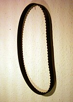
Timing belt
Timing belts with a helical offset tooth design are available. The helical offset tooth design forms a chevron pattern and causes the teeth to engage progressively. The chevron pattern design is self-aligning and does not make the noise that some timing belts make at certain speeds, and is more efficient at transferring power (up to 98%).
Disadvantages include a relatively high purchase cost, the need for specially fabricated toothed pulleys, less protection from overloading, jamming, and vibration due to their continuous tension cords, the lack of clutch action (only possible with friction-drive belts), and the fixed lengths which do not allow length adjustment (unlike link V-belts or chains).
Belt-drive cog on a belt-driven bicycle.
Specialty Belts
Belts normally transmit power on the tension side of the loop. However, designs for continuously variable transmissions exist that use belts that are a series of solid metal blocks, linked together as in a chain, transmitting power on the compression side of the loop.
Rolling Roads
Belts used for rolling roads for wind tunnels can be capable of 250 km/h.
Standard for Use
The open belt drive has parallel shafts rotating in the same direction, whereas the cross-belt drive also bears parallel shafts but rotate in opposite direction. The former is far more common, and the latter not appropriate for timing and standard V-belts unless there is a twist between each pulley so that the pulleys only contact the same belt surface. Nonparallel shafts can be connected if the belt's center line is aligned with the center plane of the pulley. Industrial belts are usually reinforced rubber but sometimes leather types, non-leather non-reinforced belts, can only be used in light applications.
The pitch line is the line between the inner and outer surfaces that is neither subject to tension (like the outer surface) nor compression (like the inner). It is midway through the surfaces in film and flat belts and dependent on cross-sectional shape and size in timing and V-belts. Calculating pitch diameter is an engineering task and is beyond the scope of this article. The angular speed is inversely proportional to size, so the larger the one wheel, the less angular velocity, and vice versa. Actual pulley speeds tend to be 0.5–1% less than generally calculated because of belt slip and stretch. In timing belts, the inverse ratio teeth of the belt contributes to the exact measurement. The speed of the belt is:
Speed = Circumference based on pitch diameter × angular speed in rpm
Selection Criteria
Belt drives are built under the following required conditions: speeds of and power transmitted between drive and driven unit; suitable distance between shafts; and appropriate operating conditions. The equation for power is:
power (kW) = (torque in newton-meters) × (rpm) × (2π radians)/(60 sec × 1000 W)
Factors of power adjustment include speed ratio; shaft distance (long or short); type of drive unit (electric motor, internal combustion engine); service environment (oily, wet, dusty); driven unit loads (jerky, shock, reversed); and pulley-belt arrangement (open, crossed, turned). These are found in engineering handbooks and manufacturer's literature. When corrected, the horsepower is compared to rated horsepowers of the standard belt cross sections at particular belt speeds to find a number of arrays that perform best. Now the pulley diameters are chosen. It is generally either large diameters or large cross section that are chosen, since, as stated earlier, larger belts transmit this same power at low belt speeds as smaller belts do at high speeds. To keep the driving part at its smallest, minimum-diameter pulleys are desired. Minimum pulley diameters are limited by the elongation of the belt's outer fibers as the belt wraps around the pulleys. Small pulleys increase this elongation, greatly reducing belt life. Minimum pulley diameters are often listed with each cross section and speed, or listed separately by belt cross section. After the cheapest diameters and belt section are chosen, the belt length is computed. If endless belts are used, the desired shaft spacing may need adjusting to accommodate standard length belts. It is often more economical to use two or more juxtaposed V-belts, rather than one larger belt.
In large speed ratios or small central distances, the angle of contact between the belt and pulley may be less than 180°. If this is the case, the drive power must be further increased, according to manufacturer's tables, and the selection process repeated. This is because power capacities are based on the standard of a 180° contact angle. Smaller contact angles mean less area for the belt to obtain traction, and thus the belt carries less power.
Belt Frictions
Belt drives depend on friction to operate, but excessive friction wastes energy and rapidly wears the belt. Factors that affect belt friction include belt tension, contact angle, and the materials used to make the belt and pulleys.
Belt Tensions
Power transmission is a function of belt tension. However, also increasing with tension is stress (load) on the belt and bearings. The ideal belt is that of the lowest tension that does not slip in high loads. Belt tensions should also be adjusted to belt type, size, speed, and pulley diameters. Belt tension is determined by measuring the force to deflect the belt a given distance per inch of pulley. Timing belts need only adequate tension to keep the belt in contact with the pulley.
Belt Wear
Fatigue, more so than abrasion, is the culprit for most belt problems. This wear is caused by stress from rolling around the pulleys. High belt tension; excessive slippage; adverse environmental conditions; and belt overloads caused by shock, vibration, or belt slapping all contribute to belt fatigue.
Belt Vibrations
Vibrations signatures are widely used for studying belt drive malfunctions. Some of the common malfunctions or faults include the effects of belt tension, speed, sheave eccentricity, and misalignment conditions.The effect of sheave Eccentricity on vibration signatures of the belt drive is quite significant. Although, vibration magnitude is not necessarily increased by this it will create strong amplitude modulation. When the top section of a belt is in resonance, the vibrations of the machine is increased. However, an increase in the machine vibration is not significant when only the bottom section of the belt is in resonance. The vibration spectrum has
Belt Dressing
Belt slippage can be addressed in several ways. Belt replacement is an obvious solution, and eventually the mandatory one (because no belt lasts forever). Often, though, before the replacement option is executed, retensioning (via pulley centerline adjustment) or dressing (with any of various coatings) may be successful to extend the belt's lifespan and postpone replacement. Belt dressings are typically liquids that are poured, brushed, dripped, or sprayed onto the belt surface and allowed to spread around; they are meant to recondition the belt's driving surfaces and increase friction between the belt and the pulleys. Some belt dressings are dark and sticky, resembling tar or syrupy, some are thin and clear, resembling mineral spirits. Some are sold to the public in aerosol cans at auto parts stores; others are sold in drums only to industrial users.
Specifications
To fully specify a belt, the material, length, and cross-section size and shape are required. Timing belts, in addition, require that the size of the teeth be given. The length of the belt is the sum of the central length of the system on both sides, half the circumference of both pulleys, and the square of the sum (if crossed) or the difference (if open) of the radii. Thus, when dividing by the central distance, it can be visualized as the central distance times the height that gives the same squared value of the radius difference on, of course, both sides. When adding to the length of either side, the length of the belt increases, in a similar manner to the Pythagorean theorem. One important concept to remember is that as D1 gets closer to D2 there is less of a distance (and therefore less addition of length) until its approaches zero.
On the other hand, in a crossed belt drive the sum rather than the difference of radii is the basis for computation for length. So the wider the small drive increases, the belt length is higher.
References
- ^ By Rhys Jenkins, Newcomen Society, (1971). Links in the History of Engineering and Technology from Tudor Times, Ayer Publishing. Page 34, ISBN 0-8369-2167-4.
- ^ James N. Boblenz. "How to lace a flat belt", Farm Collector. Retrieved 2010-04-04.
- ^ "Belt lacing patterns"(PDF). North Dakota Statue Univ.
- ^ "Flat Belt Pulleys, Belting, Splicing. Hit N Miss Enterprises. Archive from the original on 17 March 2010. Retrieved 2010-04-04.
- ^ Robert Grimshaw, Drive for Power Transmission, Cassier's MagazineVol. II, No. 9 (July 1892); pages 219-224.
- ^ John J. Flather, Rope-Driving: A treatise on the transmission of power by means of fibrousropes, Wiley, New York, 1895.
- ^ A Modern Cement Plant Installation, Power and TransmissionVol. XVIII, No 1 (Oct. 1902); pages 17-19 and 29. Note: This journal is the house organ of the Dodge Manufacturing Company and is mostly devoted rope-power systems.
- ^ Editorial staff (1916-04-15), "Radiator fans and their design", Horseless Age 37 (8): 324.
- ^ Editorial staff (1916-04-15), "S.A.E. divisions exhibit activity, Horseless Age 37 (8): 322.
- ^ DIN 7867
- ^ a b Automotive Handbook (3rd ed.). Robert Bosch GmbH 1993. p. 304. ISBN 0-8376-0330-7
- ^ "Pininfarina Aerodynamic and Aeroacoustic Research Center" Arc.pininfarina.it. Retrieved 2009-10-24.
 Media related to Belt drives at Wikimedia Commons
- Wikipedia