Published Date
Author
For further details log on website :
http://article.sapub.org/10.5923.j.cmaterials.20130304.02.html
p-ISSN: 2166-479X e-ISSN: 2166-4919
2013; 3(4): 92-99
doi:10.5923/j.cmaterials.20130304.02
Buckling Analysis of Piezolaminated Plates Using Higher Order Shear Deformation Theory
Author
Rajan L. Wankhade, Kamal M. Bajoria
Department of Civil Engineering, Indian Institute of Technology, Bombay, Mumbai, India
Correspondence to: Rajan L. Wankhade, Department of Civil Engineering, Indian Institute of Technology, Bombay, Mumbai, India.
| Email: |  |
Abstract
Abstract Buckling analysis of piezolaminated plate subjected to combined action of electro-mechanical loading is considered for the present work. Higher order shear deformation theory based finite element method is used to perform the analysis. An isoparametric eight noded element is employed in the finite element formulation. Studies are conducted for different ply orientation and plate aspect ratios of piezolaminated plate with different electric condition of the piezoelectric layer. Buckling loads are found out for simply supported piezoelectric laminated plates. Piezolaminated plates consist of cross ply symmetric and antisymmetric orientation of laminates with piezolayer attached at the top and bottom of the plate. Results presented for buckling analysis of plates are verified with other numerical solution available in the literature and further results for future references are provided.
1. Introduction
Over the last two decades plenty of work has been carried out on analysis of piezoelectric laminated structures including smart beams, columns and plates. The increased use of piezolaminated smart structures in structural application is stimulating development of different methods and solution techniques for the accurate analysis of piezolaminated structures. Some of these methods are Galerkin method, Finite element method, and Reddy’s higher order shear deformation theory. Also the experimental investigation of smart piezolaminated structures has attracted some attention. The need of such smart structures with high stiffness and low weight in engineering applications has led to the gradual replacement of many isotropic materials/structures with light weight piezo-composites. The piezoelectric material possesses a coupled electromechanical property having a direct and converse piezoelectric effect. The availability of these piezoelectric ceramics in the form of thin sheet makes them well suited for use as distributed sensors and actuators to control structural response in shape, vibration and buckling.
Berlincourt et al.[1] and Mason[2] discussed the fundamentals of piezoelectricity in brief. Takagi[3] presented definition of smart materials and structures with notable arguments and detailed comments. The limitations of classical plate theory and first order shear deformation theories forced the development of higher order theories to avoid the use of shear correction factors, to include correct cross sectional warping and to get the realistic variation of the transverse shear strains and stresses through the thickness of plate.
Tzou and Zhou[4] studied linear dynamics and distributed control of piezoelectric laminated continua. Donthireddy and Chandrashekhara[5] developed a mathematical model based on a layerwise theory for laminated composite beams with piezoelectric actuators to study its shape control. Soares et al.[6] analysed piezolaminated composite plates using refined finite element models based on higher order displacement fields and studied structural optimization. Artel and Becker[7] investigated numerically the effect of electromechanical coupling on the interlaminar stresses and the electric field strengths at free edges of piezolaminated plates. Oh and Lee[8] studied geometric nonlinear analysis of cylindrical piezolaminated shells based on the multifield layerwise theory using finite element method for the thermal and piezoelastic loading. Tzou and Gadre[9, 10] carried out theoretical analysis for vibration control of a multilayered thin shell coupled with piezoelectric actuators. Batra and Liang[11] analysed the steady state vibrations of a simply supported rectangular elastic laminated plate with embedded PZT layers. They used three dimensional linear theory of elasticity. Oh et al.[12] worked on postbuckling and vibration characteristics of piezolaminated composite plate subject to thermo-piezoelectric loads. Shen[13, 14] presented post
buckling of shear deformable laminated plates with piezoelectric actuators under complex loading condition including thermo-electro-mechanical loading. Wang[15] investigated elastic buckling of column structures with a pair of piezoelectric layers surface bonded on both sides of the columns. The governing equation coupling the piezoelectric effect was derived based on the assumed distribution of the electric potential in the flexural direction of the piezoelectric layer and an eigenvalue problem was solved using the direct difference method. Liew et al[16] carried out stability of piezoelectric FGM rectangular plates subjected to non-uniformly distributed load, heat and voltage. For carrying out analysis element free Galerkin method was employed.
In the present work stability analysis of piezolaminated plates is carried out considering higher order shear deformation theory. Piezolaminated plate studied is subjected to combined action of electromechanical loading. Linear through-the-thickness electric potential distribution is assumed for each piezoelectric sub-layer. Temperature field is assumed to be uniform for the orthotropic layers of the laminate and for piezolayer. Finite element formulation considers an isoperimetric eight noded rectangular element. Parametric studies are conducted to demonstrate the influence of boundary condition, ply orientation and plate aspect ratio on stability of piezolaminated plate with different electric condition of the piezolayer. Numerical results are presented considering simply supported and clamped piezoelectric laminated plate.
2. Finite Element Formulation
Finite element formulation is based on higher order shear deformation theory which do not need shear correction factor as that of first order shear deformation theory. And hence for considering the effect of shear deformation displacement field of HOST is assumed as follows
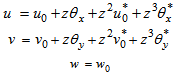 | (1) |
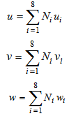
Where,  and
and  are the displacement of any point in the plate domain in x, y and z direction respectively.
  and
and  are the displacement of midpoint of normal.
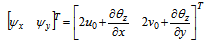
  are the rotations of normal at the middle plane in x and y direction about y and x axis respectively.
  and
and  are higher order terms which accounts cubic variation of normal.
and are the displacement of any point in the plate domain in x, y and z direction respectively. and are the displacement of midpoint of normal. are the rotations of normal at the middle plane in x and y direction about y and x axis respectively. and are higher order terms which accounts cubic variation of normal.
Figure 1. shows a piezolaminated composite plate provided with piezoelectric patches at top and bottom ssurface of the plate. Fiber can be oriented with reference to the horizontal axes and is modelled in finite element formulation.
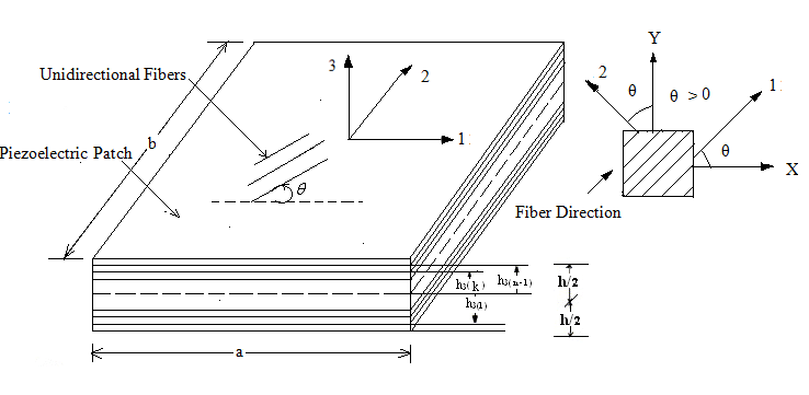 | Figure 1. Piezolaminated composite plate provided with piezoelectric patches at top and bottom surface |
Strain-Displacement Relations
The strains associated with the displacement model as per higher order shear deformation theory are given by
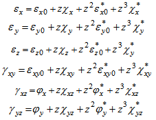 | (2) |
Where,
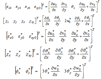
 | (3) |
Shell Element and Shape functions
8-node rectangular element is employed as shown in figure
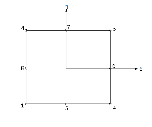 | Figure 2. Eight-nodded rectangular element |
Shape functions are given as,
For corner nodes:
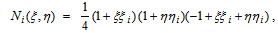
for i = 1,2,3,4
For middle edge node
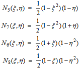 | (4) |
Displacement field
The displacement field associated with the eight nodded element can be written as
 | (5) |
Strain within the Element
Strains associated with the displacement field can be written as follow,
a. Middle plane membrane strains
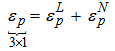 | (6) |
in which  and
and  are linear and non-linear components of middle plane membrane strains and combining linear and non-linear terms membrane strains are given as,
and are linear and non-linear components of middle plane membrane strains and combining linear and non-linear terms membrane strains are given as,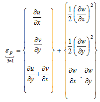 | (7) |
Curvature strains/Bending strains
Curvature strains are linearly related to bending displacement as,
 | (8) |
Shear strains,
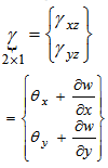 | (9) |
Thus
 | (10) |
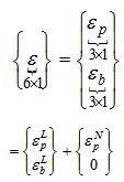
Hence,
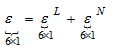 | (11) |
and shear strains can separately be written as,
 | (12) |
In which  are membrane, bending and shear components of strains respectively.
  is combined strain vector of membrane and bending strains.
  is a vector containing shear strains. Subscript ‘p’ stands for in-plane, ‘b’ for bending, ‘L’ for linear and subscript ‘N’ stands for non-linear.
are membrane, bending and shear components of strains respectively. is combined strain vector of membrane and bending strains. is a vector containing shear strains. Subscript ‘p’ stands for in-plane, ‘b’ for bending, ‘L’ for linear and subscript ‘N’ stands for non-linear.
Displacement-strain relation
Strains are related with displacements using strain displacement matrix as follows,
 | (13) |
Electro-Mechanical Coupling
For piezolaminated plates two constitutive relationships exist including the effect of mechanical and electrical loading as given by eq. 14. Variation of temperature effect is neglected in formulation.
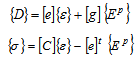 | (14) |
And hence,
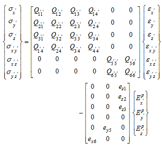 | (15) |
Where, {D} is electric displacement vector,[e] is dielectric permittivity matrix,  is the strain vector,
  is the dielectric matrix.
  is the electric field vector,
  is the stress vector and[C] is the elastic matrix for constant electric field.
is the strain vector, is the dielectric matrix. is the electric field vector, is the stress vector and[C] is the elastic matrix for constant electric field.
Electrical Potential Function
 are the electric displacement at any point in the actuator and the sensor layers, respectively, the electrical potential functions in terms of the nodal potential vector are given by
 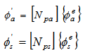 | (16) |
Where,  and
and  are the shape function matrices for the actuator and sensor layers, respectively.
  and
and  are the nodal electric potential vector for the actuator and sensor layers respectively and can be given as follow.
and are the shape function matrices for the actuator and sensor layers, respectively. and are the nodal electric potential vector for the actuator and sensor layers respectively and can be given as follow.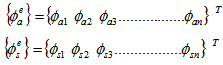 | (17) |
Stiffness Matrix Equations
Element stiffness matrix can be written as,
 | (18) |
In which
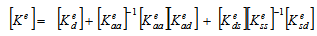 | (19) |
 | (20) |
Where,
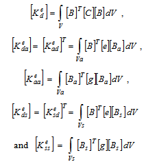 | (21) |
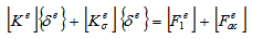
Thus the element equation in the global stiffness matrix can be written as
 | (22) |
Equilibrium and incremental Equations
Virtual displacement principle is employed to obtain equilibrium equation. Equilibrium between internal and external forces has to be satisfied. If  represents the vector of the sum of the internal and external forces.
represents the vector of the sum of the internal and external forces. 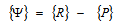 | (23) |
Where, {R} represents the external forces due to imposed load and {P} is a vector of internal resisting forces. The equilibrium state is achieved when  .
.
.  | (24) |
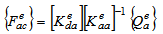
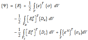
Where V, Va and Vs are the area of the entire structure, sensor layer and actuator layer respectively. Considering the work done by external forces due to the applied surface traction and applied electric charge on actuator the equation for external work done can be written as
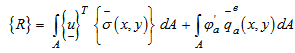 | (25) |
Stability equation
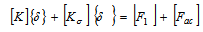
The geometric stiffness matrix is associated with the x and y coordinates. The characteristic equation of stability is written as,
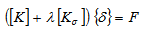 | (26) |
 | (27) |
Where, the lowest magnitude of eigen value gives critical buckling load and the vector  represents the buckled mode shape. And the eigen value problem is solved to get buckling loads.
represents the buckled mode shape. And the eigen value problem is solved to get buckling loads.  | (28) |
3. Results and Discussions
Buckling analysis of piezolaminated plates have been carried out for different ply orientation considering symmetric and antisymmetric cross-ply lamination schemes. Buckling of smart piezolaminated plate is examined subjected to uniform axial compressive force at the edges. Furthermore for piezolaminated plate, critical mechanical buckling loads are obtained for different thickness to span ratios of piezolaminated plates and for closed and open loop electric condition.
3.1. Buckling of Simply Supported Square Multilayered Plate (00/900…)n
|
 ) for simply supported multilayered cross ply laminated plate
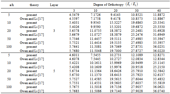
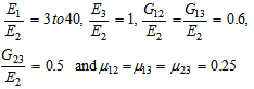
Effect of orthotropy is studied for simply supported square multilayered plate subjected to a uniform uniaxial compressive force at the edges. Laminated plate is having cross ply orientation of layers. Critical buckling loads are tabulated in Table 1 for effect of orthotropy of individual layers, the ratio of span to thickness (a/h) and the number of layers of simply supported square multilayered composite plates. Material property adopted is as follow.
Results are found in good agreement with that of refined finite element solution given by Owen and Li [17].
3.2. Buckling of Simply Supported Square Piezoelectric Laminated Plate (p/00/900/900/00/p)
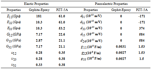
The piezoelectric laminate with piezolayer attached at the top and bottom of the plate is subjected to a uniaxial uniform edge compressive force Nx. Hence a square piezoelectric laminated plate of thickness of 0.01 m and side length ‘a’ is having simply supported boundary on all four edges. The laminate consists of a (p/00/900/900/00/p) Graphite-Epoxy sublaminate provided with two PZT-5A attached on outer surface of the plate. Each piezoelectric layer has thickness of 0.1h, whereas each elastic layer has a thickness of 0.2h. Elastic and piezoelectric material properties are as shown in table 2.
|
The effect of span to thickness ratio on critical uniaxial buckling load (Nxa2/E2.h3) of simply supported square laminated plate with different electric condition is shown in figure 3.
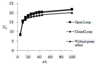 | Figure 3. Effect of span to thickness ratio on normalized critical buckling load of simply supported symmetric cross ply piezolaminated plate (p/00/900/900/00/p) |
From figure 3 it can be observed that critical buckling load increases for piezoelectric effect. Also piezoelectricity has little effect on the buckling load of the laminates with closed-circuits than that of open loop. There is an increase of 7.9 % in critical buckling load for piezolaminated plate than that of without piezoeffect. Hence critical buckling load can be considerably increases if plate is subjected to piezoeffect. For lesser vaues of a/h ratio % variation in critical buckling load is found to be 3.3 % for open loop electric condition than that of closed loop.
3.3. Buckling of Simply Supported Square Piezoelectric Laminated Plate (p/00/900/00/900/p)
Simply supported square piezolaminates with piezolayer attached at the top and bottom of the plate is subjected to a uniaxial uniform edge compressive force Nx. Piezoelectric laminated plate is having a thickness of 0.01 m and side length ‘a’. The laminate consists of antisymmetric ply orientation of Graphite-Epoxy sublaminate provided with two PZT-5A attached on outer surfaces of the plate. Material properties of Graphite-Epoxy and PZT-5A are same as previous example. Each piezoelectric layer has thickness of 0.1h, whereas each elastic layer has a thickness of 0.2h. Figure 4 shows effect of span to thickness ratio on critical mechanical buckling load (Nxa2/E2.h3) of piezolaminated plate with different electric conditions.
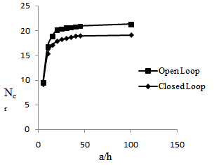 | Figure 4. Effect of span to thickness ratio on normalized critical buckling load of simply supported antisymmetric cross ply piezolaminated plate (p/00/900/00/900/p) |
Significant increase in critical buckling load is observed for open loop electric condition than that of closed loop. Thus piezoelectricity has little effect on the buckling load of the laminates with closed-circuits in this case. The increase in critical buckling load is found to be 8.09 %, 11.05 % and 10.19 % for open loop circuit than that of closed loop for a/h = 10, 20 and 100 respectively.
4. Conclusions
A finite isoparametric element for the mechanical displacement field is combined with an electric potential field to consider piezoelectric effect. Parametric study is conducted to demonstrate the influence of boundary condition, ply orientation and plate aspect ratio on stability of piezolaminated plate with different electric condition of the piezolayer. For symmetric cross ply piezolaminated plate % increase in critical buckling load is found to be 7.9 % than that of without piezoeffect. Thus considering piezoeffect bucklibg load can be considerably increased.
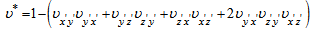
Appendix: Stiffness Coefficients of the Laminated Plate According to The Higher Order Shear Deformation Theory
The stiffness coefficients according to the HOST are as follows
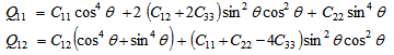
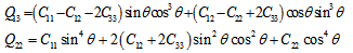
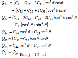
Where,
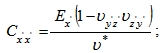 ;
; 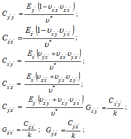 ;
;
And
References
For further details log on website :
http://article.sapub.org/10.5923.j.cmaterials.20130304.02.html


No comments:
Post a Comment