A composite material (also called a composition material or shortened to composite) is a material made from two or more constituent materials with significantly different physical or chemical properties that, when combined, produce a material with characteristics different from the individual components. The individual components remain separate and distinct within the finished structure. The new material may be preferred for many reasons: common examples include materials which are stronger, lighter, or less expensive when compared to traditional materials. More recently, researchers have also begun to actively include sensing, actuation, computation and communication into composites, which are known as Robotic Materials.
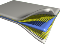

Composites are formed by combining materials together to form an overall structure that is better than the sum of the individual components.
Typical engineered composite materials include:
- mortars, concrete
- Reinforced plastics, such as fiber-reinforced polymer
- Metal composites
- Ceramic composites (composite ceramic and metal matrices)
Composite materials are generally used for buildings, bridges, and structures such as boat hulls, swimming pool panels, race car bodies, shower stalls, bathtubs, storage tanks, imitation granite and cultured marble sinks and countertops. The most advanced examples perform routinely on spacecraft and aircraft in demanding environments.
History
The earliest man-made composite materials were straw and mud combined to form bricks for building construction. Ancient brick-making was documented by Egyptian tomb paintings.
Wattle and daub is one of the oldest man-made composite materials, at over 6000 years old. Concrete is also a composite material, and is used more than any other man-made material in the world. As of 2006, about 7.5 billion cubic metres of concrete are made each year—more than one cubic metre for every person on Earth.
- Woody plants, both true wood from trees and such plants as palms and bamboo, yield natural composites that were used prehistorically by mankind and are still used widely in construction and scaffolding.
- Plywood 3400 BC by the Ancient Mesopotamians; gluing wood at different angles gives better properties than natural wood
- Cartonnage layers of linen or papyrus soaked in plaster dates to the First Intermediate Period of Egypt c. 2181–2055 BC and was used for death masks.
- Cob (material) Mud Bricks, or Mud Walls, (using mud (clay) with straw or gravel as a binder) have been used for thousands of years.
- Concrete was described by Vitruvius, writing around 25 BC in his Ten Books on Architecture, distinguished types of aggregate appropriate for the preparation of lime mortars? For structural mortars, he recommended pozzolana, which were volcanic sands from the sandlike beds of Pozzuoli brownish-yellow-gray in colour near Naples and reddish-brown at Rome. Vitruvius specifies a ratio of 1 part lime to 3 parts pozzolana for cements used in buildings and a 1:2 ratio of lime to pulvis Puteolanus for underwater work, essentially the same ratio mixed today for concrete used at sea. Natural cement-stones, after burning, produced cements used in concretes from post-Roman times into the 20th century, with some properties superior to manufactured Portland cement.
- Papier-mâché, a composite of paper and glue, has been used for hundreds of years
- The first artificial fibre reinforced plastic was bakelite which dates to 1907, although natural polymers such as shellac predate it
- One of the most common and familiar composite is fiberglass, in which small glass fiber are embedded within a polymeric material (normally an epoxy or polyester). The glass fiber is relatively strong and stiff (but also brittle), whereas the polymer is ductile (but also weak and flexible). Thus the resulting fiberglass is relatively stiff, strong, flexible, and ductile.

Concrete is a mixture of cement and aggregate, giving a robust, strong material that is very widely used.

Plywood is used widely in construction
Concrete is the most common artificial composite material of all and typically consists of loose stones (aggregate) held with a matrix of cement. Concrete is an inexpensive material, and will not compress or shatter even under quite a large compressive force. However, concrete cannot survive tensile loading (i.e., if stretched it will quickly break apart). Therefore, to give concrete the ability to resist being stretched, steel bars, which can resist high stretching forces, are often added to concrete to form reinforced concrete.
Fibre-reinforced polymers or FRPs include carbon-fiber-reinforced polymer or CFRP, and glass-reinforced plastic or GRP. If classified by matrix then there are thermoplastic composites, short fiber thermoplastics, long fibre thermoplastics or long fibre-reinforced thermoplastics. There are numerous thermoset composites, including paper composite panels. Many advanced systems usually incorporate aramid fibre and carbon fibre in an epoxy resin matrix.

Composite sandwich structure panel used for testing at NASA

"Structural Integrity Analysis : Composites" (PDF).
Shape memory polymer composites are high-performance composites, formulated using fibre or fabric reinforcement and shape memory polymer resin as the matrix. Since a shape memory polymer resin is used as the matrix, these composites have the ability to be easily manipulated into various configurations when they are heated above their activation temperatures and will exhibit high strength and stiffness at lower temperatures. They can also be reheated and reshaped repeatedly without losing their material properties. These composites are ideal for applications such as lightweight, rigid, deployable structures; rapid manufacturing; and dynamic reinforcement.
High strain composites are another type of high-performance composites that are designed to perform in a high deformation setting and are often used in deployable systems where structural flexing is advantageous. Although high strain composites exhibit many similarities to shape memory polymers, their performance is generally dependent on the fiber layout as opposed to the resin content of the matrix.
Composites can also use metal fibres reinforcing other metals, as in metal matrix composites (MMC) or ceramic matrix composites (CMC), which includes bone (hydroxyapatite reinforced with collagen fibres), cermet (ceramic and metal) and concrete. Ceramic matrix composites are built primarily for fracture toughness not for strength.
Organic matrix/ceramic aggregate composites include asphalt concrete, polymer concrete, mastic asphalt, mastic roller hybrid, dental composite, syntactic foam and mother of pearl. Chobham, armour is a special type of composite armour used in military applications.
Additionally, thermoplastic composite materials can be formulated with specific metal powders resulting in materials with a density range from 2 g/cm³ to 11 g/cm³ (same density as lead). The most common name for this type of material is "high gravity compound" (HGC), although "lead replacement" is also used. These materials can be used in place of traditional materials such as aluminium, stainless steel, brass, bronze, copper, lead, and even tungsten in weighting, balancing (for example, modifying the centre of gravity of a tennis racquet), vibration damping, and radiation shielding applications. High density composites are an economically viable option when certain materials are deemed hazardous and are banned (such as lead) or when secondary operations costs (such as machining, finishing, or coating) are a factor.
A sandwich-structured composite is a special class of composite material that is fabricated by attaching two thin but stiff skins to a lightweight but thick core. The core material is normally low strength material, but its higher thickness provides the sandwich composite with high bending stiffness with overall low density.
Wood is a naturally occurring composite comprising cellulose fibres in a lignin and hemicellulose matrix. Engineered wood includes a wide variety of different products such as wood fibre board, plywood. oriented strand board, wood plastic composite (recycled wood fibre in polyethylene matrix), Pykrete (sawdust in ice matrix), Plastic-impregnated or laminated paper or textiles, Arborite, Formica (plastic) and Micarta. Other engineered laminate composites, such as Mallite, use a central core of end grain balsa wood, bonded to surface skins of light alloy or GRP. These generate low-weight, high rigidity materials.
Tufcot is a composite engineering material manufactured from synthetic fibres and thermosetting resins. All grades of Tufcot are available with solid lubricant incorporated. The various grades contain either Graphite, P.T.F.E, Ceramic Powder or Molybdenum Disulphide dispersed evenly throughout the material, so that the wear of a components surface continually releases further lubricant. It offers the design engineer an attractive alternative to traditional materials used throughout industry for bushes, bearings, wear pads, and many more applications.It’s only 1/6th the weight of steel, is easily machined and has exceptional dimensional stability, even in wet conditions. Tufcot is a highly recommended composite material for use where other forms of lubricant are either not desirable, intermittent or non-existent. In addition, in numerous cases where the maintenance of lubricant films is difficult this type of material has been found to give improved performance. Special performance or properties such as fire retardance and acid resistance can be obtained by variations in either resin or fabric reinforcement.
Products
Fiber-reinforced composite materials have gained popularity (despite their generally high cost) in high-performance products that need to be lightweight, yet strong enough to take harsh loading conditions such as aerospace, components (tails, wings, fuselages, propellers), boat and scull hulls, bicycle frames and racing car bodies. Other uses include fishing rods, storage tanks, swimming pool panels, and baseball bats. The new Boeing 787 structure including the wings and fuselage is composed largely of composites. Composite materials are also becoming more common in the realm of orthopedic surgery.
Carbon composite is a key material in today's launch vehicles and heat shields for the re-entry phase of spacecraft. It is widely used in solar panel substrates, antenna reflectors and yokes of spacecraft. It is also used in payload adapters, inter-stage structures and heat shields of launch vehicles. Furthermore, disk brake systems of airplanes and racing cars are using carbon/carbon material, and the composite material with carbon fibers and silicon carbide matrix has been introduced in luxury vehicles and sports cars.
In 2006, a fiber-reinforced composite pool panel was introduced for in-ground swimming pools, residential as well as commercial, as a non-corrosive alternative to galvanized steel.
In 2007, an all-composite military Humvee was introduced by TPI Composites Inc and Armor Holdings Inc, the first all-composite military vehicle. By using composites the vehicle is lighter, allowing higher payloads. In 2008, carbon fiber and DuPont Kevlar (five times stronger than steel) were combined with enhanced thermoset resins to make military transit cases by ECS Composites creating 30-percent lighter cases with high strength.
Pipes and fittings for various purpose like transportation of potable water, fire-fighting, irrigation, seawater, desalinated water, chemical and industrial waste, and sewage are now manufactured in glass reinforced plastics.
Overview
Carbon fiber composite part.
Composites are made up of individual materials referred to as constituent materials. There are two main categories of constituent materials: matrix and reinforcement. At least one portion of each type is required. The matrix material surrounds and supports the reinforcement materials by maintaining their relative positions. The reinforcements impart their special mechanical and physical properties to enhance the matrix properties. A synergism produces material properties unavailable from the individual constituent materials, while the wide variety of matrix and strengthening materials allows the designer of the product or structure to choose an optimum combination.
Engineered composite materials must be formed to shape. The matrix material can be introduced to the reinforcement before or after the reinforcement material is placed into the mould cavity or onto the mould surface. The matrix material experiences a melding event, after which the part shape is essentially set. Depending upon the nature of the matrix material, this melding event can occur in various ways such as chemical polymerization or solidification from the melted state.
A variety of moulding methods can be used according to the end-item design requirements. The principal factors impacting the methodology are the natures of the chosen matrix and reinforcement materials. Another important factor is the gross quantity of material to be produced. Large quantities can be used to justify high capital expenditures for rapid and automated manufacturing technology. Small production quantities are accommodated with lower capital expenditures but higher labour and tooling costs at a correspondingly slower rate.
Many commercially produced composites use a polymer matrix material often called a resin solution. There are many different polymers available depending upon the starting raw ingredients. There are several broad categories, each with numerous variations. The most common are known as polyester, vinyl ester, epoxy, phenolic, polyimide, polyamide, polypropylene, PEEK and others. The reinforcement materials are often fibres but also commonly ground minerals. The various methods described below have been developed to reduce the resin content of the final product, or the fibre content is increased. As a rule of thumb, lay up results in a product containing 60% resin and 40% fibre, whereas vacuum infusion gives a final product with 40% resin and 60% fiber content. The strength of the product is greatly dependent on this ratio.
Martin Hubbe and Lucian A Lucia consider wood to be a natural composite of cellulose fibres in a matrix of lignin.
ConstituentsMatrices
Organic
Polymers are common matrices (especially used for fiber reinforced plastics). Road surfaces are often made from asphalt concrete which uses bitumen as a matrix. Mud (wattle and daub) has seen extensive use. Typically, most common polymer-based composite materials, including fiberglass, carbon fiber, and Kevlar, include at least two parts, the substrate and the resin.
Polyester resin tends to have yellowish tint, and is suitable for most backyard projects. Its weaknesses are that it is UV sensitive and can tend to degrade over time, and thus generally is also coated to help preserve it. It is often used in the making of surfboards and for marine applications. Its hardener is a peroxide, often MEKP (methyl ethyl ketone peroxide). When the peroxide is mixed with the resin, it decomposes to generate free radicals, which initiate the curing reaction. Hardeners in these systems are commonly called catalysts, but since they do not re-appear unchanged at the end of the reaction, they do not fit the strictest chemical definition of a catalyst.
Vinylester resin tends to have a purplish to bluish to greenish tint. This resin has lower viscosity than polyester resin, and is more transparent. This resin is often billed as being fuel resistant, but will melt in contact with gasoline. This resin tends to be more resistant over time to degradation than polyester resin, and is more flexible. It uses the same hardeners as polyester resin (at a similar mix ratio) and the cost is approximately the same.
Epoxy resin is almost totally transparent when cured. In the aerospace industry, epoxy is used as a structural matrix material or as a structural glue.
Shape memory polymer (SMP) resins have varying visual characteristics depending on their formulation. These resins may be epoxy-based, which can be used for auto body and outdoor equipment repairs; cyanate-ester-based, which are used in space applications; and acrylate-based, which can be used in very cold temperature applications, such as for sensors that indicate whether perishable goods have warmed above a certain maximum temperature. These resins are unique in that their shape can be repeatedly changed by heating above their glass transition temperature (Tg). When heated, they become flexible and elastic, allowing for easy configuration. Once they are cooled, they will maintain their new shape. The resins will return to their original shapes when they are reheated above their Tg. The advantage of shape memory polymer resins is that they can be shaped and reshaped repeatedly without losing their material properties. These resins can be used in fabricating shape memory composites.
InorganicCement (concrete), metals, ceramics and sometimes glass. Unusual matrices such as ice are sometime proposed as in pykecrete.
Reinforcement

Differences in the way the fibers are laid out give different strengths and ease of manufacture.
Fiber
Reinforcement usually adds rigidity and greatly impedes crack propagation. Thin fibers can have very high strength, and provided they are mechanically well attached to the matrix they can greatly improve the composite's overall properties.
Fiber-reinforced composite materials can be divided into two main categories normally referred to as short fiber-reinforced materials and continuous fiber-reinforced materials. Continuous reinforced materials will often constitute a layered or laminated structure. The woven and continuous fibre styles are typically available in a variety of forms, being pre-impregnated with the given matrix (resin), dry, uni-directional tapes of various widths, plain weave, harness satins, braided, and stitched.
The short and long fibers are typically employed in compression moulding and sheet moulding operations. These come in the form of flakes, chips, and random mate (which can also be made from a continuous fibre laid in random fashion until the desired thickness of the ply / laminate is achieved).
Common fibers used for reinforcement include glass fibers, carbon fibers, cellulose (wood/paper fiber and straw) and high strength polymers for example aramid. Silicon carbide fibers are used for some high temperature applications.
Other ReinforcementConcrete uses aggregate, and reinforced concrete additionally uses steel bars (rebar) to tension the concrete. Steel mesh or wires are also used in some glass and plastic products.
Cores
Many composite layup designs also include a co-curing or post-curing of the prepreg with various other media, such as honeycomb or foam. This is commonly called a sandwich structure. This is a more common layup for the manufacture of radomes, doors, cowlings, or non-structural parts.
Open- and closed-cell-structured foams like polyvinylchloride, polyurethane, polyethylene or polystyrene foams, balsa wood, syntactic foams, and honeycombs are commonly used core materials. Open- and closed-cell metal foam can also be used as core materials.
Fabrication Methods
Fabrication of composite materials is accomplished by a wide variety of techniques, including:
- Advanced fiber placement (Automated fiber placement)
- Tailored fiber placement
- Fiberglass spray lay-up process
- Filament winding
- Lanxide process
- Tufting
- Z-pinning
Composite fabrication usually involves wetting, mixing or saturating the reinforcement with the matrix, and then causing the matrix to bind together (with heat or a chemical reaction) into a rigid structure. The operation is usually done in an open or closed forming mold, but the order and ways of introducing the ingredients varies considerably.
Mold Overview
Within a mold, the reinforcing and matrix materials are combined, compacted, and cured (processed) to undergo a melding event. After the melding event, the part shape is essentially set, although it can deform under certain process conditions. For a thermoset polymeric matrix material, the melding event is a curing reaction that is initiated by the application of additional heat or chemical reactivity such as an organic peroxide. For a thermoplastic polymeric matrix material, the melding event is a solidification from the melted state. For a metal matrix material such as titanium foil, the melding event is a fusing at high pressure and a temperature near the melting point.
For many moulding methods, it is convenient to refer to one mould piece as a "lower" mould and another mould piece as an "upper" mould. Lower and upper refer to the different faces of the moulded panel, not the mould's configuration in space. In this convention, there is always a lower mould, and sometimes an upper mould. Part construction begins by applying materials to the lower mould. Lower mould and upper mould are more generalized descriptors than more common and specific terms such as male side, female side, a-side, b-side, tool side, bowl, hat, mandrel, etc. Continuous manufacturing uses a different nomenclature.
The moulded product is often referred to as a panel. For certain geometries and material combinations, it can be referred to as a casting. For certain continuous processes, it can be referred to as a profile.
Vacuum Bag Moulding
Vacuum bag moulding uses a flexible film to enclose the part and seal it from outside air. Vacuum bag material is available in a tube shape or a sheet of material. A vacuum is then drawn on the vacuum bag and atmospheric pressure compresses the part during the cure. When a tube shaped bag is used, the entire part can be enclosed within the bag. When using sheet bagging materials, the edges of the vacuum bag are sealed against the edges of the mould surface to enclose the part against an air-tight mould. When bagged in this way, the lower mold is a rigid structure and the upper surface of the part is formed by the flexible membrane vacuum bag. The flexible membrane can be a reusable silicone material or an extruded polymer film. After sealing the part inside the vacuum bag, a vacuum is drawn on the part (and held) during cure. This process can be performed at either ambient or elevated temperature with ambient atmospheric pressure acting upon the vacuum bag. A vacuum pump is typically used to draw a vacuum. An economical method of drawing a vacuum is with a venturi vacuum and air compressor.
A vacuum bag is a bag made of strong rubber-coated fabric or a polymer film used to compress the part during cure or hardening. In some applications the bag encloses the entire material, or in other applications a mold is used to form one face of the laminate with the bag being a single layer to seal to the outer edge of the mold face. When using a tube shaped bag, the ends of the bag are sealed and the air is drawn out of the bag through a nipple using a vacuum pump. As a result, uniform pressure approaching one atmosphere is applied to the surfaces of the object inside the bag, holding parts together while the adhesive cures. The entire bag may be placed in a temperature-controlled oven, oil bath or water bath and gently heated to accelerate curing.
Vacuum bagging is widely used in the composites industry as well. Carbon fiber fabric and fiberglass. along with resins and epoxies are common materials laminated together with a vacuum bag operation.
Woodworking Application
In commercial woodworking facilities, vacuum bags are used to laminate curved and irregular shaped workpieces.
Typically, polyurethane or vinyl materials are used to make the bag. A tube shaped bag is open at both ends. The piece, or pieces to be glued are placed into the bag and the ends sealed. One method of sealing the open ends of the bag is by placing a clamp on each end of the bag. A plastic rod is laid across the end of the bag, the bag is then folded over the rod. A plastic sleeve with an opening in it, is then snapped over the rod. This procedure forms a seal at both ends of the bag, when the vacuum is ready to be drawn.
A "platen" is sometimes used inside the bag for the piece being glued to lie on. The platen has a series of small slots cut into it, to allow the air under it to be evacuated. The platen must have rounded edges and corners to prevent the vacuum from tearing the bag.
When a curved part is to be glued in a vacuum bag, it is important that the pieces being glued be placed over a solidly built form, or have an air bladder placed under the form. This air bladder has access to "free air" outside the bag. It is used to create an equal pressure under the form, preventing it from being crushed.
Pressure Bag MoldingThis process is related to vacuum bag molding in exactly the same way as it sounds. A solid female mold is used along with a flexible male mold. The reinforcement is placed inside the female mold with just enough resin to allow the fabric to stick in place (wet lay up). A measured amount of resin is then liberally brushed indiscriminately into the mold and the mold is then clamped to a machine that contains the male flexible mold. The flexible male membrane is then inflated with heated compressed air or possibly steam. The female mold can also be heated. Excess resin is forced out along with trapped air. This process is extensively used in the production of composite helmets due to the lower cost of unskilled labor. Cycle times for a helmet bag moulding machine vary from 20 to 45 minutes, but the finished shells require no further curing if the molds are heated.
Autoclave Moulding
A process using a two-sided mould set that forms both surfaces of the panel. On the lower side is a rigid mould and on the upper side is a flexible membrane made from silicone or an extruded polymer film such as nylon. Reinforcement materials can be placed manually or robotically. They include continuous fibre forms fashioned into textile constructions. Most often, they are pre-impregnated with the resin in the form of prepreg fabrics or unidirectional tapes. In some instances, a resin film is placed upon the lower mould and dry reinforcement is placed above. The upper mould is installed and vacuum is applied to the mould cavity. The assembly is placed into an autoclave. This process is generally performed at both elevated pressure and elevated temperature. The use of elevated pressure facilitates a high fibre volume fraction and low void content for maximum structural efficiency.
Resin Transfer Moulding RTM)
RTM is a process using a rigid two-sided mould set that forms both surfaces of the panel. The mould is typically constructed from aluminum or steel, but composite molds are sometimes used. The two sides fit together to produce a mould cavity. The distinguishing feature of resin transfer moulding is that the reinforcement materials are placed into this cavity and the mould set is closed prior to the introduction of matrix material. Resin transfer moulding includes numerous varieties which differ in the mechanics of how the resin is introduced to the reinforcement in the mould cavity. These variations include everything from the RTM methods used in out of autoclave composite manufacturing for high-tech aerospace components to vacuum infusion (for resin infusion see also boat building) to vacuum assisted resin transfer moulding (VARTM). This process can be performed at either ambient or elevated temperature.
Other Fabrication Methods
Other types of fabrication include press moulding, transfer moulding, pultrusion moulding, filament winding, casting, centrifugal casting, continuous casting and slip forming. There are also forming capabilities including CNC filament winding, vacuum infusion, wet lay-up, compression moulding, and thermoplastic moulding, to name a few. The use of curing ovens and paint booths is also needed for some projects.
Finishing Methods
The finishing of the composite parts is also critical in the final design. Many of these finishes will include rain-erosion coatings or polyurethane coatings.
Tooling
The mold and mold inserts are referred to as "tooling." The mold/tooling can be constructed from a variety of materials. Tooling materials include invar, steel, aluminium, reinforced silicone rubber, nickel, and carbon fiber. Selection of the tooling material is typically based on, but not limited to, the coefficient of thermal expansion, expected number of cycles, end item tolerance, desired or required surface condition, method of cure, glass transition temperature of the material being moulded, moulding method, matrix, cost and a variety of other considerations.
Physical Properties
The physical properties of composite materials are generally not isotropic (independent of direction of applied force) in nature, but rather are typically anisotropic (different depending on the direction of the applied force or load). For instance, the stiffness of a composite panel will often depend upon the orientation of the applied forces and/or moments. Panel stiffness is also dependent on the design of the panel. For instance, the fibre reinforcement and matrix used, the method of panel build, thermoset versus thermoplastic, type of weave, and orientation of fibre axis to the primary force.
In contrast, isotropic materials (for example, aluminium or steel), in standard wrought forms, typically have the same stiffness regardless of the directional orientation of the applied forces and/or moments.
The relationship between forces/moments and strains/curvatures for an isotropic material can be described with the following material properties: Young's Modulus, the shear Modulus and the Poisson's ratio, in relatively simple mathematical relationships. For the anisotropic material, it requires the mathematics of a second order tensor and up to 21 material property constants. For the special case of orthogonal isotropy, there are three different material property constants for each of Young's Modulus, Shear Modulus and Poisson's ratio—a total of 9 constants to describe the relationship between forces/moments and strains/curvatures.
Techniques that take advantage of the anisotropic properties of the materials include mortise and tenon joints (in natural composites such as wood) and Pi Joints in synthetic composites.
Failure
Shock, impact, or repeated cyclic stresses can cause the laminate to separate at the interface between two layers, a condition known as delamination. Individual fibres can separate from the matrix e.g. fibre pull-out.
Composites can fail on the microscopic or macroscopic scale. Compression failures can occur at both the macro scale or at each individual reinforcing fiber in compression buckling. Tension failures can be net section failures of the part or degradation of the composite at a microscopic scale where one or more of the layers in the composite fail in tension of the matrix or failure of the bond between the matrix and fibers.
Some composites are brittle and have little reserve strength beyond the initial onset of failure while others may have large deformations and have reserve energy absorbing capacity past the onset of damage. The variations in fibers and matrices that are available and the mixtures that can be made with blends leave a very broad range of properties that can be designed into a composite structure. The best known failure of a brittle ceramic matrix composite occurred when the carbon-carbon composite tile on the leading edge of the wing of the Space Shuttle Columbia fractured when impacted during take-off. It led to catastrophic break-up of the vehicle when it re-entered the Earth's atmosphere on 1 February 2003.
Compared to metals, composites have relatively poor bearing strength.
TestingTo aid in predicting and preventing failures, composites are tested before and after construction. Pre-construction testing may use finite element analysis (FEA) for ply-by-ply analysis of curved surfaces and predicting wrinkling, crimping and dimpling of composites. Materials may be tested during manufacturing and after construction through several nondestructive methods including ultrasonics, thermography, shearography and X-ray radiography, and laser bond inspection for NDT of relative bond strength integrity in a localized area.
References
- ^ M. A. McEvoy and N. Correll. Materials that couple sensing, actuation, computation and communication. Science 347(6228), 2015.
- ^ Shaffer, G.D. "An Archaeomagnetic Study of a Wattle and Daub Building Collapse." Journal of Field Archaeology, 20, No. 1. Spring, 1993. 59-75. JSTOR. Accessed 28 January 2007.
- ^ "Minerals commodity summary – cement – 2007". US United States Geological Survey. 1 June 2007. Retrieved 16 January 2008.
- ^ Heather Lechtman and Linn Hobbs "Roman Concrete and the Roman Architectural Revolution", Ceramics and Civilization Volume 3: High Technology Ceramics: Past, Present, Future, edited by W.D. Kingery and published by the American Ceramics Society, 1986; and Vitruvius, Book II:v,1; Book V:xii2
- ^ "Composite Materials. Tufcot Engineering Ltd. Retrieved 2016-03-09.
- ^ "Material Grades. Tufcot Engineering Ltd. Retrieved 2016-03-09.
- ^http://www.ncsu.edu/bioresources/BioRes_02/BioRes_02_4_534_535_Hubbe_L_BioResJ_Editorial_LoveHate.pdf.
- ^ David Hon and Nobuo Shiraishi, eds. (2001) Wood and cellulose chemistry, 2nd ed. (New York: Marcel Dekker), p. 5 ff.
- ^ "Vacuum Bags For Woodworking".
- ^ Waterman, Pamela J. "The Life of Composite Materials". Desktop Engineering Magazine. April 2007.
- ^ Matzkanin, George A.; Yolken, H. Thomas. "Techniques for the Nondestructive Evaluation of Polymer Matrix Composites", (PDF). AMMTIAC Quarterly 2 (4).
- Robert M. Jones (1999). Mechanics of Composite Materials (2nd ed.). Taylor & Francis. ISBN 9781560327127.
- Autar K. Kaw (2005). Mechanics of Composite Materials (2nd ed.). CRC. ISBN 0-8493-1343-0.
- Handbook of Polymer Composites for Engineers By Leonard Hollaway Published 1994 Woodhead Publishing
- Matthews, F.L. & Rawlings, R.D. (1999). Composite Materials: Engineering and Science. Boca Raton: CRC Press. ISBN 0-8493-0621-3.
- Wikipedia