Blog List

Wednesday, 13 April 2016

SAW SET

Saw set is a term applied to various forms of a tool used in the tuning and sharpening of saw blades. The saw set is used to adjust the set, or distance the saw tooth is bent away from the saw blade.


Morrill-style saw set.

Purpose
When the teeth of a saw are formed from the body, they are in line and the same thickness as the blade immediately behind them. A saw with this configuration is described as having 'no' or '0' set.
Labeled cross-section diagram of a saw blade.
To prevent the body of the blade binding and for other enhancements to the cutting action, the teeth can be set (angled out) from the blade. Teeth can be set in several patterns: single-sided set, alternating set or a patterned set. Most Western and Asian handsaws use an alternating set, whereby a tooth is set the opposite direction from the preceding one. Specialized tools like veneer saws or flush-cut saws may be set only to one side. Some hacksaws and machine saw blades have patterned sets that may require specially designed saw sets to create.
See Saw and Sawfiler for more detailed information about set, kerf, and maintenance of saws.
A saw set makes the process of setting the teeth easier, more consistent or both.
Categories of saw set

Saw sets come in many forms: from improvised to intricate, specially designed mechanisms. The demand for a more capable saw set is clear, as from 1810 to 1925 almost 900 different saw sets were patented. Saw sets can be categorized by the mechanical principle under which they operate.

Hammer

The essential components of this type of saw set are an anvil and a striking tool, often a hammer. These tools range from common blacksmith's equipment to specially designed and marketed saw sets


Fig. A - Illustration of a Setting-Block.
This process could use any anvil with a suitable surface and any striking tool of appropriate size. The saw tooth to be set is angled over an edge of the anvil and struck in the direction the tooth is to be set.
Hammering the teeth against an anvil is also used to remove set from the teeth either for maintenance or fresh setting.


Fig. B - Illustration of an Atkins Criterion Saw set.
Another form uses either a bevel-edged anvil or setting block so that the saw blade rests on a flat portion of the anvil and the tooth held over the bevel, to be struck until bent to the desired angle (Fig. A). Its use is described by the following:
"...lay the block, Fig. [A], in some convenient flat place and hold the tooth of saw so that the point projects over the beveled surface fully one-quarter of an inch. Give two or three strokes with a light hammer, striking the tooth always about one-quarter of an inch from the point. Regulate the set by the use of set gauge..."
Following the same mechanics of operation, some designs introduced either a pin or lever aligned over the tooth that could be struck with a hammer. Rather than rely on the accuracy of the operator, such a device ensures only the portion of the saw under the pin is bent (Fig. B).
Lever and Plate
This type of saw set can be called lever, plate, wrest, spring or comb. The plate that forms the body of the tool is fitted over the saw and levered perpendicular to the saw blade which springs or bends the tooth to an angle. The name comb likely refers to versions with many slots which bears resemblance to a comb for hair.
Fig. C - Illustration of a Revolving Saw-Set.
The simplest form of a lever saw set is a plate, usually of metal, thick enough to only fit over one tooth at a time and notched to a depth less than that of the tooth. To more easily create a consistent set, a stop of some form is added to the design ensuring the tool be levered to the same angle on each tooth. These stops (also, stop blocks) can be adjustable as in the case of the thumbscrews on the saw set in Fig. C.
One advantage of this design is that many lever saw sets can bend the tooth either direction. An alternating set can be made without turning the saw or saw set around as is generally necessary with Hammer or Pliers style saw sets.
Pliers

Regular pliers with small jaws could be used to set a tooth. Designers added to this to make pliers with a built in stop (Fig. D). The stop is usually adjustable and rests against the saw blade as the jaws bend the tooth. The goal of the stop is to make a consistent set and prevent tooth breakage. Depending on the style, the tooth is either gripped first in the jaws and then bent or the saw set is aligned to the tooth and the jaws closed.

Fig. D - Basic pliers-style saw set.

Two- Handled
Two-handled, or pistol-grip saw sets use the action of two handles closing to move cams or plungers. A pistol-grip style tool is most often what is thought of as a saw set in contemporary discussions of saw maintenance, especially amongst hand tool enthusiasts.
Stanley 42W "pistol-grip" saw set.
The inventor Charles Morrill introduced a saw set with a plunger based on his patent. This design, as well as improvements added to it, came into prolific use and in the United States are frequently found with woodworking tools. An image of a Morrill design saw set is found at the introduction of the article. The plunger (also, pin) pushes against the saw tooth when the handles are squeezed together. The other face of the saw tooth rests against an anvil and the whole saw blade is held at the desired angle to the anvil by a stop or rest. On most designs both the anvil and the rest are adjustable.
Another milestone was the introduction of the Taintor "positive" saw set. It utilizes a multi-position anvil and a special cam that clamps to the blade before the plunger pushes against the tooth. The cam was designed to prevent the saw set moving once aligned with a tooth.
Using the same mechanical design as the Morrill or Taintor saw sets, several manufacturers repositioned the handles to be held parallel to the blade, rather than perpendicular as with the original Morrill design. This is the form referred to as pistol-grip, due to its mild resemblance to the profile of a pistol. This form includes the 42 series from Stanley (X,W and 442), an E. C. Stearns design, as well as some contemporary saw sets.
Automated
Automated saw sets use machine automation rather than the user to move the setting mechanism between teeth. The mechanized nature should also apply the same pressure to each tooth.
Some of these machines were designed by manufacturers, such as US Pat. 29,772 and 47,806 by various members of the Disston family. Others were made for sharpening shops (either independent or a department of a company) to increase efficiency. Foley is known to have produced saw-setting machines targeted at saw sharpening shops.
References

  1. ^ Friberg, Todd. Patent American Saw Sets. Osage Press.
  2. ^ Disston & Sons, Henry (1902). Handbook for Lumbermen.
  3. a b Fridberg, Todd (September 1995). "Collecting Saw Sets".The Tool Shed 88. Retrieved 25 July 2012.
  4. ^ Conley, Mark. "What is a saw set".The Saw Set Collector's Resource. Retrieved 25 July 2012.
  5. ^ U.S. Patent 375,088.

- Wikipedia 
How to Get Rid of Belly Fat in a Week

You're fed up with your belly fat, and you want it gone -- now. Your abdomen didn't expand in one week, so you can't expect it to slim down in that short time either. Use a week to introduce measures to help you lose belly fat over time and reduce bloating. You might feel a little lighter after seven days, but true loss of fat will take several weeks or months.

How to Get Rid of Belly Fat in a Week

Don't expect a significant loss of fat in a week. Photo Credit amanaimagesRF/amana images/Getty Images


How to Lose Belly Fat

Belly fat is a metabolically active type of fat that sits deep inside the abdominal cavity. It surrounds internal organs and releases compounds that make you vulnerable to metabolic disturbances, heart disease and inflammation.

Belly fat may be dangerous, but it's also responsive to traditional weight-loss strategies of diet and exercise. One pound of fat equals 3,500 calories; thus, to lose a pound, you must consume 3,500 calories fewer than you burn. In a week, you can't afford much more than a 3,500- or 7,000-calorie deficit without severely depriving yourself of nutrients and solid food. This deficit means you'll lose 1 or 2 pounds per week.

Some people can lose more than 2 pounds in a week with a dedicated fitness program and serious dietary restrictions.The time and effort required to lose weight that quickly is grueling and usually unsustainable, though. Even if you can lose a notable amount of weight in a week, a lot of it will be water weight -- not true belly fat. Weight you lose quickly is likely to be regained quickly too.
Exercise to Lose Belly Fat
Belly fat is usually the first weight lost when you start an exercise program, explains Rush University Medical Center. If you are new to exercise or coming back from a long hiatus, you can't expect to hit the gym for hours at a time to burn off fat that first week. This only increases your risk of injury and burn out.

Instead, build up to at least 150 minutes per week of moderate-intensity cardio, such as swimming, jogging or hiking. A duration of 250 minutes per week will lead to more significant weight loss, explains the American College of Sports Medicine. This means 250 minutes a week for several weeks or months, though; you're unlikely to see dramatic results after one week.

Strength training is another critical component in belly fat loss. You can't crunch your tummy away, but you can participate in a full-body strength-training program that addresses all the major muscle groups. Do this at least twice a week to build muscle, which helps boost your metabolism. The results of strength-training are gradual, however. One week of strength training won't induce the changes in your body necessary to improve your metabolism, but over the long haul you'll see improvements.


Dietary Changes to Reduce Visceral Fat

Belly fat also responds to a lower-calorie diet that's full of healthy, unprocessed foods. Go for lean protein, fresh produce and whole grains at meals. When you have just a week to lose as much as possible, ban all sweetened drinks -- including soda and juice -- bakery treats and ice cream. Also avoid refined grains, such as pizza and white bread, as well as alcohol. Keep your portion sizes to just 2 to 4 ounces for meats and other proteins and about 1/2 cup for grains. Over the long term, these dietary revisions help you drop belly fat.

Resist the urge to use a diet that promises quick results. Often they don't work, or they're so restrictive you can't handle them for more than a couple of days -- let alone a week. If you do stick to the plan, you may very well see a drop in pounds -- but it's not from a substantial amount of fat; it's mostly from water. A quick-fix diet teaches you nothing about sensible eating that will help you manage your belly fat and health forever. You'll likely gain all the weight back as soon as you resume your normal eating habits.

Reduce Bloating This Week

Although you can't lose substantial fat in a week, you can jump start the weight-loss process. Also make a few dietary and lifestyle changes to reduce bloating so your tummy feels flatter.

Avoid over stuffing yourself at meals; eat small meals throughout the day. Chewing gum and drinking with a straw can cause excess air to gather in the digestive tract. Carbonated beverages, spicy foods, large servings of beans or cruciferous vegetables, dried fruits and fruit juice often induce gas and bloating. If you're lactose intolerant, avoid dairy products to help reduce belly swelling; make sure you obtain important nutrients, such as calcium and vitamin D, from milk alternatives or other fortified foods.
www.livestrong.com

ULTIMATE TENSILE STRENGTH (UTS)

Ultimate tensile strength (UTS), often shortened to tensile strength (TS) or ultimate strength, is the capacity of a material or structure to withstand loads tending to elongate, as opposed to compressive strength, which withstands loads tending to reduce size. In other words, tensile strength resists tension (being pulled apart), whereas compressive strength resists compression (being pushed together). Ultimate tensile strength is measured by the maximum stress that a material can withstand while being stretched or pulled before breaking. In the study of strength of materials, tensile strength, compressive strength, and shear strength can be analyzed independently.
Some materials break very sharply, without plastic deformation, in what is called a brittle failure. Others, which are more ductile, including most metals, experience some plastic deformation and possibly necking before fracture.

Two vises apply tension to a specimen by pulling at it, stretching the specimen until it fails. The maximum stress it withstands before failing is its ultimate tensile strength.
The UTS is usually found by performing a tensile test and recording the engineering stress versus strain. The highest point of the stress–strain curve (see point 1 on the engineering stress/strain diagrams below) is the UTS. It is an intensive property; therefore its value does not depend on the size of the test specimen. However, it is dependent on other factors, such as the preparation of the specimen, the presence or otherwise of surface defects, and the temperature of the test environment and material.
Tensile strengths are rarely used in the design of ductile members, but they are important in brittle members. They are tabulated for common materials such as alloys, composite materials, ceramics, plastics and wood.
Tensile strength can be defined for liquids as well as solids under certain conditions. For example, when a tree draws water from its roots to its upper leaves by transpiration, the column of water is pulled upwards from the top by the cohesion of the water in the xylem, and this force is transmitted down the column by its tensile strength. Air pressure, osmotic pressure, and capillary tension also plays a small part in a tree's ability to draw up water, but this alone would only be sufficient to push the column of water to a height of less than ten metres, and trees can grow much higher than that (over 100m).
Tensile strength is defined as a stress, which is measured as force per unit area. For some non-homogeneous materials (or for assembled components) it can be reported just as a force or as a force per unit width. In the International System of Units (SI), the unit is the pascal (Pa) (or a multiple thereof, often megapascals (MPa), using the SI prefix mega); or, equivalently to pascals, newtons per square metre (N/m²). A United States customary unit is pounds per square inch (lb/in² or psi), or kilo-pounds per square inch (ksi, or sometimes kpsi), which is equal to 1000 psi; kilo-pounds per square inch are commonly used in one country (USA), when measuring tensile strengths.
Concept
Ductile Materials


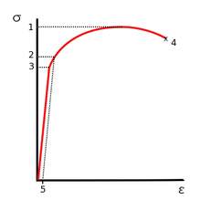
"Engineering" stress–strain (σ–ε) curve typical of aluminum
1. Ultimate strength
2. Yield strength
3. Proportional limit stress
4. Fracture
5. Offset strain (typically 0.2%)
Many materials can display linear elastic behavior, defined by a linear stress–strain relationship, as shown in the left figure up to point 3. The elastic behavior of materials often extends into a non-linear region, represented in the figure by point 2 (the "yield point"), up to which deformations are completely recoverable upon removal of the load; that is, a specimen loaded elastically in tension will elongate, but will return to its original shape and size when unloaded. Beyond this elastic region, for ductile materials, such as steel, deformations are plastic. A plastically deformed specimen does not completely return to its original size and shape when unloaded. For many applications, plastic deformation is unacceptable, and is used as the design limitation.


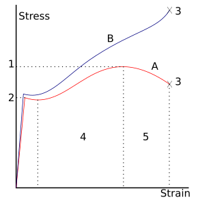
"Engineering" (red) and "true" (blue) stress–strain curve typical of structural steel.
  • 1: Ultimate strength
  • 2: Yield strength (yield point)
  • 3: Rupture
  • 4: Strain hardening region
  • 5: Necking region
  • A: Apparent stress (F/A0)
  • B: Actual stress (F/A
After the yield point, ductile metals undergo a period of strain hardening, in which the stress increases again with increasing strain, and they begin to neck, as the cross-sectional area of the specimen decreases due to plastic flow. In a sufficiently ductile material, when necking becomes substantial, it causes a reversal of the engineering stress–strain curve (curve A, right figure); this is because the engineering stress is calculated assuming the original cross-sectional area before necking. The reversal point is the maximum stress on the engineering stress–strain curve, and the engineering stress coordinate of this point is the ultimate tensile strength, given by point 1.
The UTS is not used in the design of ductile static members because design practices dictate the use of the yield stress. It is, however, used for quality control, because of the ease of testing. It is also used to roughly determine material types for unknown samples.
The UTS is a common engineering parameter when designing brittle members, because there is no yield point.
Testing
Typically, the testing involves taking a small sample with a fixed cross-sectional area, and then pulling it with a tensometer at a constant strain (change in gauge length divided by initial gauge length) rate until the sample breaks.
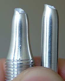
Round bar specimen after tensile stress testing.
When testing some metals, indentation hardness correlates linearly with tensile strength. This important relation permits economically important nondestructive testing of bulk metal deliveries with lightweight, even portable equipment, such as hand-held Rockwell hardness testers. This practical correlation helps quality assurance in metalworking industries to extend well beyond the laboratory and universal testing machines.
It should be noted that, while most metal forms, such as sheet, bar, tube, and wire, can exhibit the test UTS, fibers, such as carbon fibers, being only 2/10,000th of an inch in diameter, must be made into composites to create useful real-world forms. As the datasheet on T1000G below indicates, while the UTS of the fiber is very high at 6,370MPa, the UTS of a derived composite is 3,040MPa - less than half the strength of the fiber.
Typical tensile strengths
Typical tensile strengths of some materials
MaterialYield strength
(MPa)
Ultimate tensile strength
(MPa)
Density
(g/cm³)
Steel, structural ASTM A36 steel250400-5507.8
Steel, 1090 mild2478417.58
Human skin15202
Steel, 2800 Maraging steel261726938.00
Steel, AerMet 340216024307.86
Steel, Sandvik Sanicro 36Mo logging cable precision wire175820708.00
Steel, AISI 4130, water quenched 855 °C (1570 °F), 480 °C (900 °F) temper95111107.85
Steel, API 5L X654485317.8
Steel, high strength alloy ASTM A5146907607.8
Acrylic clear cast sheet (PMMA)721141.16
High-density polyethylene (HDPE)26-33370.85
Polypropylene12-4319.7-800.91
Steel, stainless AISI 302 - cold-rolled520 8608.19
Cast iron 4.5% C, ASTM A-48130200
"Liquidmetal" alloy1723550-16006.1
Beryllium 99.9% Be3454481.84
Aluminium alloy 2014-T64144832.8
Polyester resin (unreinforced)55
Polyester and chopped strand mat laminate 30% E-glass100
S-Glass epoxy composite2358
Aluminium alloy 6061-T62413002.7
Copper 99.9% Cu702208.92
Cupronickel 10% Ni, 1.6% Fe, 1% Mn, balance Cu1303508.94
Brass200 +5508.73
Tungsten941151019.25
Glass332.53
E-GlassN/A1500 for laminates,
3450 for fibers alone
2.57
S-GlassN/A47102.48
Basalt fiberN/A48402.7
MarbleN/A152.6
ConcreteN/A2-52.7
Carbon fiberN/A1600 for laminates,
4137 for fibers alone
1.75
Carbon fiber (Toray T1000G) (the strongest man-made fibres)6370 fibre alone1.80
Human hair10
Bamboo350-5000.4
Spider silk (see note below)10001.3
Spider silk, Darwin's bark spider1652
Silkworm silk5001.3
Aramid (Kevlar or Twaron)362037571.44
UHMWPE24520.97
UHMWPE fibers (Dyneema or Spectra)2300-35000.97
Vectran2850-3340
Polybenzoxazole (Zylon)270058001.56
Wood, pine (parallel to grain)40
Bone (limb)104-1211301.6
Nylon, molded, type 6/645751.15
Nylon fiber, drawn9001.13
Epoxy adhesive-12 - 30-
Rubber-16
BoronN/A31002.46
Silicon, monocrystalline (m-Si)N/A70002.33
Ultra-pure silica glass fiber-optic strands4100
Sapphire (Al2O3)400 at 25 °C, 275 at 500 °C, 345 at 1000 °C19003.9-4.1
Boron nitride nanotubeN/A33000 ?
Diamond160028003.5
GrapheneN/A1300001.0
First carbon nanotube ropes ?36001.3
Colossal carbon tubeN/A70000.116
Carbon nanotube (see note below)N/A11000-630000.037-1.34
Carbon nanotube compositesN/A1200N/A
High-strength carbon nanotube filmN/A9600N/A
Iron (pure mono-crystal)37.874
Limpet Patella vulgata teeth (Goethite)4900
3000-650


A) Many of the values depend on manufacturing process and purity/composition.

B) Multiwalled carbon nanotubes have the highest tensile strength of any material yet measured, with labs producing them at a tensile strength of 63 GPa, still well below their theoretical limit of 300 GPa. The first nanotube ropes (20mm in length) whose tensile strength was published (in 2000) had a strength of 3.6 GPa. The density depends on the manufacturing method, and the lowest value is 0.037 or 0.55 (solid).

C)nThe strength of spider silk is highly variable. It depends on many factors including kind of silk (Every spider can produce several for sundry purposes.), species, age of silk, temperature, humidity, swiftness at which stress is applied during testing, length stress is applied, and way the silk is gathered (forced silking or natural spinning). The value shown in the table, 1000 MPa, is roughly representative of the results from a few studies involving several different species of spider however specific results varied greatly.

D) Human hair strength varies by ethnicity and chemical treatments.

Typical properties for annealed elements
ElementYoung's
modulus
(GPa)
Offset or
yield strength
(MPa)
Ultimate
strength
(MPa)
silicon1075000–9000
tungsten411550550–620
iron21180–100350
titanium120100–225246–370
copper130117210
tantalum186180200
tin479–1415–200
zinc (wrought)105110–200
nickel170140–350140–195
silver83170
gold79100
aluminium7015–2040-50
lead1612
References

  1. ^ Degarmo, Black & Kohser 2003, p. 31
  2. ^ Smith & Hashemi 2006, p. 223
  3. ^ For a review, see Harvey Brown "The theory of the rise of sap in Trees: Some Historical and Conceptual Remarks" in Physics in Perspective vol 15 (2013) p 320-358
  4. a b "Tensile Properties". Retrieved 20 February 2015.
  5. ^ E.J. Pavlina and C.J. Van Tyne, "Correlation of Yield Strength and Tensile Strength with Hardness for Steels", Journal of Materials Engineering and Performance, 17:6 (December 2008)
  6. a b "Properties of Carbon Fiber Tubes". Retrieved 20 February 2015.
  7. ^ "MatWeb - The Online Materials Information Resource". Retrieved 20 February 2015.
  8. ^ "MatWeb - The Online Materials Information Resource". Retrieved 20 February 2015.
  9. ^ "MatWeb - The Online Materials Information Resource". Retrieved 20 February 2015.
  10. ^ "MatWeb - The Online Materials Information Resource". Retrieved 20 February 2015.
  11. ^ USStubular.com.
  12. ^ IAPD Typical Properties of Acrylics
  13. ^ strictly speaking this figure is the flexural strength (or modulus of rupture), which is a more appropriate measure for brittle materials than "ultimate strength."
  14. ^ "MatWeb - The Online Materials Information Resource". Retrieved 20 February 2015.
  15. ^ "MatWeb - The Online Materials Information Resource" . Retrieved 20 February 2015.
  16. a b "Guide to Glass Reinforced Plastic (fibreglass) - East Coast Fibreglass Supplies". Retrieved 20 February 2015.
  17. ^ "Soda-Lime (Float) Glass Material Properties :: MakeItFrom.com", Retrieved 20 February 2015.
  18. ^ "Basalt Continuous Fibers". Archived from the original, on 2009-12-29. Retrieved 2009-12-29.
Further Reading

  • Giancoli, Douglas, Physics for Scientists & Engineers Third Edition (2000). Upper Saddle River: Prentice Hall.
  • Köhler T, Vollrath F (1995). "Thread biomechanics in the two orb-weaving spiders Araneus diadematus (Araneae, Araneidae) and Uloboris walckenaerius (Araneae, Uloboridae)". Journal of Experimental Zoology 271: 1–17. doi:10.1002/jez.1402710102.
  • T Follett, Life without metals
  • Min-Feng Y, Lourie O, Dyer MJ, Moloni K, Kelly TF, Ruoff RS (2000). "Strength and Breaking Mechanism of Multiwalled Carbon Nanotubes Under Tensile Load". Science 287(5453): 637–640. Bibcode:2000Sci...287..637Y,  doi:10.1126/science.287.5453.637,  PMID 10649994.
  • George E. Dieter, Mechanical Metallurgy (1988). McGraw-Hill, UK.

- Wikipedia 

Advantages and Disadvantages of Fasting for Runners

Author BY   ANDREA CESPEDES  Food is fuel, especially for serious runners who need a lot of energy. It may seem counterintuiti...